Optronic systems can be used in a wide variety of fields, including surveillance, defense, industry, food processing and healthcare. These systems need to be tested during design, manufacture, calibration and installation. It is therefore essential to characterize them in the laboratory.
Introduction
In this article, we talk about how to characterize an optronic system (thermal and visible sensors) in the laboratory. The aim is to quantify the performance of a camera. When we talk about a camera, we're actually talking about the entire image chain: optics, sensor, acquisition and conversion electronics, image processing, display screen and even the observer'seye!
Please note that we won't go into detail about the parameters measured, as this is not the purpose of this article. However, they will be documented for those who want to know more.
Equipment used to characterize optronic systems
To characterize an optronic system, we generally need an optical bench composed as follows:
- an optical table, mounted on 4 shock-absorbing feet
- a collimator with a long focal length (typically F=1000 mm) and a large exit pupil diameter (e.g. D=145 mm)
- a six-position motorized test pattern wheel with the following test patterns:
- two 0.3 and 1 mrad diameter hole sights for optical axis measurement
- two inclined vertical and horizontal half-moon test patterns for MTF measurement
- a 15×15 mrad square test pattern for NETD measurement
- MRTD pattern with different frequency patterns 0.5, 1, 1.5, 2.5 and 4 cy/mrad
- an absolute and differential blackbody consisting of a transmitter head and a controller for managing temperature setpoints
- an electronics cabinet to control and power all electrical equipment
Methods and measurements on the optical bench
For all parameters, the principle is the same: the collimator is used to obtain an image of a test pattern on the sensor (considered at infinity). The pattern is illuminated by a homogeneous light source for visible sensors, or by the black body for infrared sensors. Digital processing then automatically processes the images, extracting data from the perceived signal for the operator's standardized interpretation.
On this type of optical bench, it is useful to measure a certain number of parameters depending on the spectral band, such as :
- NETD(Noise Equivalent Temperature Difference)
- FOV(Field Of View)
- MTF(Modulation Transfer Function)
- MRTD(Minimum Resolvable Temperature Difference)
- NUC(Non Uniformity Correction)
- RMS(Root Mean Square)
- optical distortion
- optical and mechanical alignment
Generally, when characterizing an optronic system, all these measurements are carried out in succession to refine understanding of the system and determine its precise specifications. For example, when responding to a call for tenders based on specifications, this is the best way to justify the technical aspects of the proposed system.
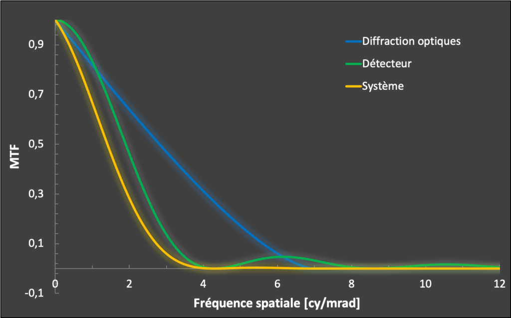
Experimental curves can then be compared with theoretical ones. For example, the graph below shows the theoretical MTF curves for a system, its optics and detector. It is then easy to superimpose the experimental MTF measurement and compare it with the yellow curve. In this way, the quality of the system can be judged on the basis of its intrinsic parameters.
Conclusion
I hope you are now convinced that these measurements are essential to characterize an optronic system operating in the visible light or infrared spectrum.
In the field of military surveillance and defense, MRTD measurements are then used to experimentally estimate Detection, Reconnaissance and Identification (DRI) distances based on a specific target.
If you're interested in characterizing an optronic system, we've got the equipment and the know-how. So why not contact us?
If you'd like to find out more about Imasolia's solutions, please visit this page. Feel free to leave me a comment below, I'll be delighted to reply.

Ping: Optical design and dimensioning of imaging systems